"Does anyone have any information or experience with this small
Trimble GPSDO?"
I had previously posted that what I thought these boards
were and how they might work and said I was waiting for 2
of these boards that I had ordered to arrive. Yesterday the
2 boards arrived in an Epacket from China. If you order
more than one board check them carefully on arrival because
the 2 I received were placed back-to-back with no padding
in between and a couple of the small SMD components on the
back side were partially ripped off the pc board. Fortunately
the damage was repairable and both boards are ok. What I found
was that there are at least 2 different versions of this GPSDO
and although both function the same, the location of some
of the parts differ.
First, there is the understandable language barrier and if
the sellers do have information that could help you get the
board up and running, it isn't included in the English
listings. Some of the info you can glean from looking at all
of the photos of the various units for sale on Ebay is just
from arrows on the photos telling where to connect power and
get the 10Mhz output. It took me a lot of trial and error plus
tracing out some of the runs to get to a point of where the
boards were working as intended.
The supply voltage required is stated to be 5.6 to 6VDC and
this goes to an LT1764A low dropout regulator set to 5VDC out
so my 'guess' is that 6VDC should be the minimum supply voltage
to make sure the regulator keeps working properly. With the
multicontact connector facing you you will see a 5A fuse near
the back right edge of the connector. I soldered the '+' supply
lead from my power supply (that puts out about 6.3VDC regulated)
to the left end of this fuse and the '-' supply lead to the ground
plane on the left of the connector. Using too high an input VDC
could cause the regulator to dissipate too much heat.
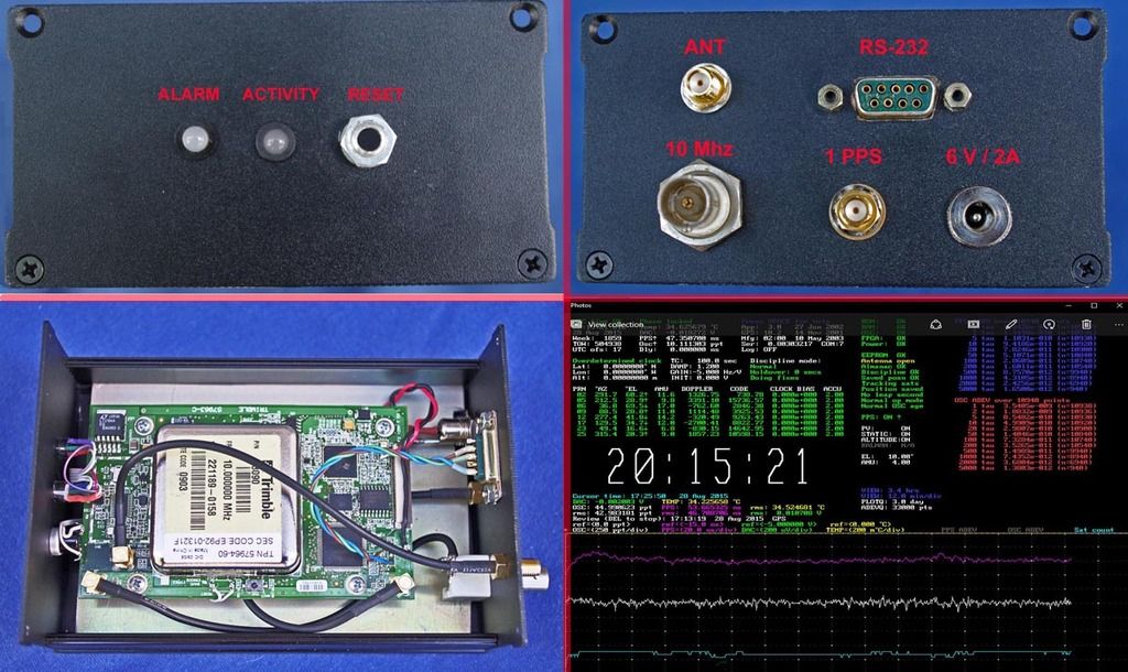
When the board is powered up with the antenna and the 10Mhz
output connected you will see no 10Mhz output. There are two
2-color LEDs on the board, on top of one version, and on the
bottom of the other version. One is the ALARM LED and the other
is the ACTIVITY LED. On power-up both light red then go out
(if all is well) then the ACT LED stays on solid green for maybe
10 minutes until the GPS receiver starts to track satellites. At
this point the ACT LED starts to flash a slow green and the 10Mhz
output is turned on. After a few more minutes when the board
achieves lock the ACT LED starts flashing green at a higher rate.
On the left front corner of the board is the 1 PPS connector.
To the right of that connector are 4 unpopulated holes for a
connector. I traced those out and found 2 went to a RS-232
chip that appears to be a different type depending on which of
the boards you receive. The left hole is ground (RS-232 pin 5
on the computer end), then the next hole is not connected, then
RS-232 pin 2, then pin 3 being the hole with the square index pad
on the right. Using a terminal emulator program and 57600 8N1N
I was able to communicate with the board. Typing '?' will give
you a long list of all the commands it will accept. For instance,
'STAT' and 'POSSTAT' are 2 of the commands that will give you
info on how the board is working. Typing *IDN? at the UCCM-P >
prompt returns 57964-60 for my board and POSSTAT shows up to 12
satellites can be tracked. The date code on my unit is 2009.
The board seems to work well but the OCXO runs pretty hot so it
probably isn't a double oven. The multicontact connector probably
has most of the functions and LED signals available but I couldn't
see using it so I'll get whatever signals I want directly off the
pc board.
-Arthur
_______________________________________________
time-nuts mailing list -- time-***@febo.com
To unsubscribe, go to https://www.febo.com/cgi-bin/mailman/listinfo/time-nuts
and follow the instructions there.